Building Information Modeling (BIM); Driving Collaboration and Efficiency
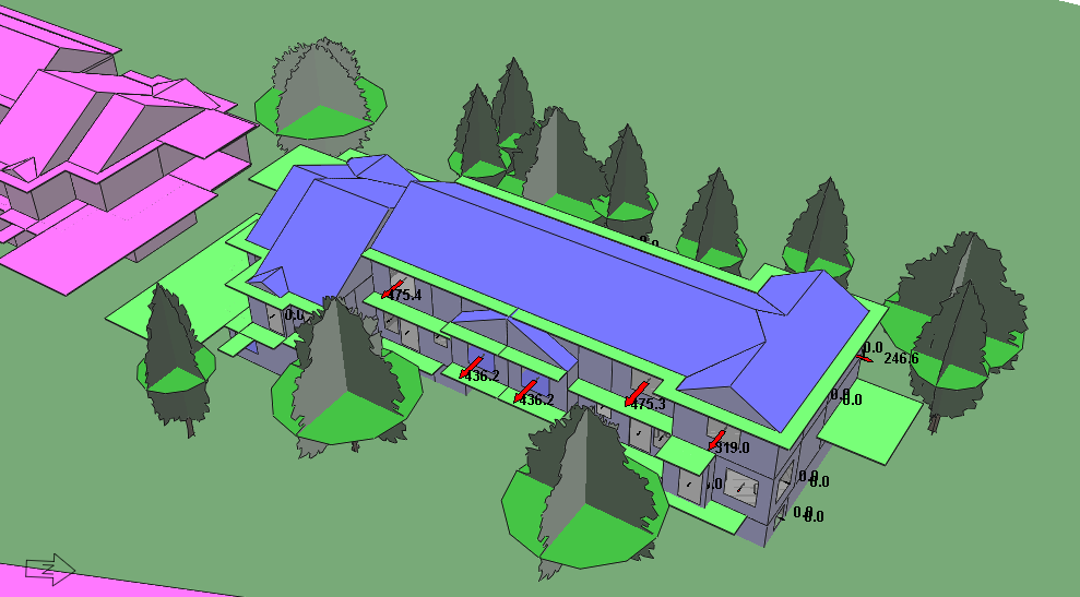
- BIM enhances early stage design coordination using preconstruction visualization
- This allows for better collaboration & coordination, during the design process
- Results in reduced schedule, costs, and errors during construction
What is BIM?
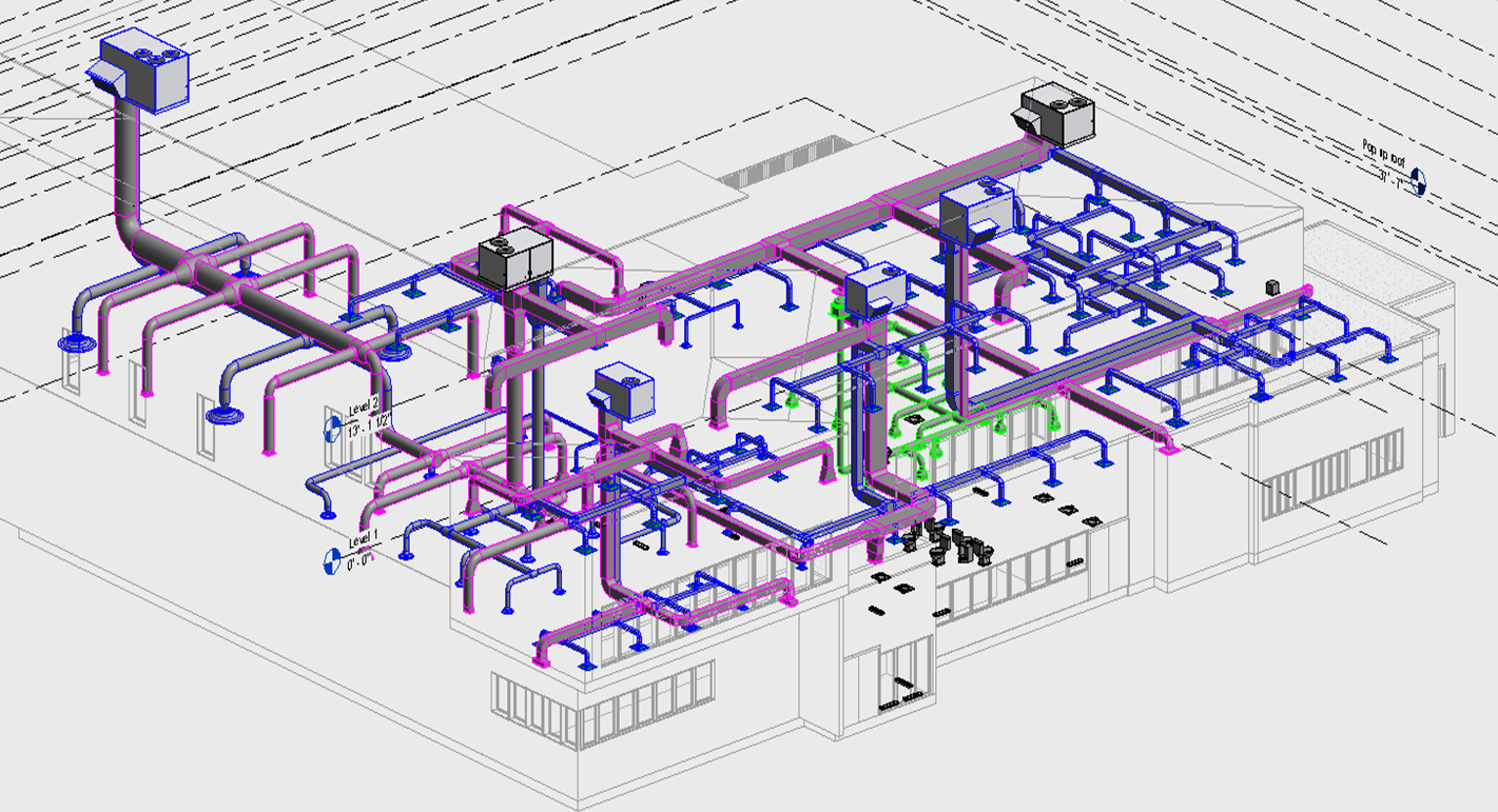
Building Information Modeling (BIM) is a process for creating and managing information on a construction project across its lifecycle. It is a collaborative process which results in a Building Information Model which can be used as a design visualization tool, to analyze and optimize workflows, costs, and operations.
Benefits
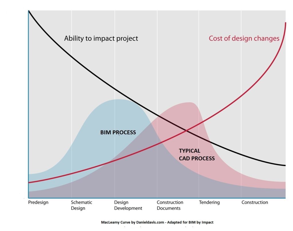
The BIM process enables early stage design collaboration, analysis, and information management. In moving the design and coordination process forward, the cost of any design changes are minimized.
The benefit is represented in a graph known as the “MacLeamy curve” which was originally developed to visualize the benefits of an Integrated Design Process.
The result is a highly coordinated model which allows for optimization of the workflows during construction and operation.
Level of Developments (LOD)
Level of Development (LOD) is an industry standard which defines the detail and refinement of the Building Information Model (BIM) at various stages in the design and construction process. The LOD definitions were originally developed by the Architecture Institute of America (AIA) and further refined by the industry accepted BIMforum’s LOD Specification guide. The definitions are as follows:
LOD 100 – Conceptual; The Model Element may be graphically represented in the Model with a symbol or other generic representation.
LOD 200 – Approximate Geometry; The Model Element is graphically represented within the Model as a generic system, object, or assembly with approximate quantities, size, shape, location, and orientation.
LOD 300 – Precise Geometry; The Model Element is graphically represented within the Model as a specific system, object, or assembly in terms of quantity, size, shape, location, and orientation.
LOD 350 – Precise Geometry with Connections; The Model Element is graphically represented within the Model as a specific system, object, or assembly in terms of quantity, size, shape, location, orientation, and interfaces with other building systems.
LOD 400 – Fabrication Ready Geometry; The Model Element is graphically represented within the Model as a specific system, object, or assembly in terms of size, shape, location, quantity, and orientation with detailing, fabrication, assembly, and installation information.
LOD 500 – Operational/As-built Models; The Model Element is a field verified representation in terms of size, shape, location, quantity, and orientation.
Design Efficiency
At Impact Engineering we understand the value of BIM in optimizing the delivery of our projects in an efficient and well-coordinated process, resulting in improved outcomes during the design and construction phases. We are fully committed to the collaborative approach that BIM embodies through regular coordination meetings and communication.
Impact Engineering uses modeling software such as Autodesk Revit and is capable of delivering 3D models that conform to industry standard BIM management frameworks and Level of Developments (LOD).
Opportunities
Please feel free to reach out to Senior Engineer, Jason Le if you would like to further understand the benefits of BIM.